
The DaviSound TB-1 "Inner Tube" Tool Box
On-Line Owners Manual And Applications Data
Copyright © 2001 - 2005 by DaviSound - ALL RIGHTS RESERVED!
|
|
PLEASE READ THIS IN ENTIRETY BEFORE TURNING ON YOUR UNIT!
Overview
The TB-1 was the first DaviSound "Inner Tube" built, originally back in 1982. Pictured herein is the latest evolution of the design, circa 2001.
Note that slight modifications, including tube type, were introduced in 2005!
The few who have seen and heard these latest versions say there is just no way to convey the magnificent look, feel and sound of this box without experiencing it personally.
This "manual" then is for those who would just like to enrich that experience with a thorough working knowledge of this unique piece of professional equipment beforehand.
Going against the "grain" (pardon the "WG" pun!) of DaviSound design philosophy, this is one unit which was designed NOT to be "transparent".
This design incorporates a three section amplifier with each stage chosen to complement the next to offer a subtle, but discernible "sound character" which is mostly defined by the presence of rich even harmonics, mostly "fat tubey" second harmonic content. THD is typically around 1% per cent, or less, but compared to the typical .001%, or less, THD of standard DaviSound circuitry, this is, of course, quite high , and audible, by comparison.
Any overload of the chain occurs at the tube stage where it goes into slight asymmetrical compression when over-driven thus contributing the musical harmonic "overtones" to the signal. Tube stage second harmonic distortion can run as high as 5%, or higher, when over-driven. In other words, it gives that classic "touch of glass" ... "tube warmth" that many feel is desirable for certain signal processing applications.
Furthermore, it offers a fully discreet transistor Class A output stage designed very similarly to the classic line amplifier stages of some of those infamous European recording consoles of the late sixties/early seventies, save for the lower noise of today's transistors employed for voltage gain. This section utilizes an acclaimed DaviSound "DaviSirkits MasterPiece" MP-4 single-ended circuit block module for each channel's final output stage.
Combine this with an active Low-Noise FET front-end, differentially input balanced, and you have some "colorful" amplifier!
And, the rich styling, that some have likened to the impression of a dashboard instrument panel in an early model, imported sportscar, certainly enhances the aesthetic appeal as a most appropriate housing for such classic amplifier circuitry.
Like our other Tool Boxes, these units are each entirely hand-made originals and, many advisors and appraisors concur, these are especially destined to appreciate in value in years to come!
Your unit has been Hand-signed and dated by Hayne Davis inside the cabinet upon final testing and certification just prior to shipment.
Features
The TB-1 offers the unusual combination of both FRONT AND REAR XLR Microphone Input Jacks for the balanced front-end. This allows your choice of using the TB-1 in a permanent rack installation with studio connectors wired to the rear panel and, at the same time, it facillitates front panel mic plug-in when desired. Of course you should NOT attempt to plug mics into both the front and rear jacks at the same time!
This "Inner Tube" model also offers a front-panel, normally closed switching 1/4" phone jack as an instrument input. When an electric instrument is plugged in, the balanced microphone front-end is disconnected from the chain and the TIP of the plug is routed directly to the triode tube stage and then to the subsequent, discreet Class A output buffer.
This feature instantly turns the TB-1 into a tube input stage, instrument direct box.
The single gain control with the upper mounted black knob is located between the tube output and the input of the transistor block.
The lighted Modutec (or similar) VU Meters take their signal from a comparator driven sample of the output signal and offer front-panel, selectable signal operation. The mini-toggle switch beneath each meter selects calibrated -10 db = OVU in the LEFT toggle position ... with +4 db operation in the RIGHT toggle position.
It is a tradition on DaviSound "Inner Tubes" to employ a "tube port" window in the center of the control panel so that the warm glow of the tube is visible. This is nice, both for aesthetics reasons and for practical reasons as well, in order to note the operating condition of the tube filaments.
There is also a larger access port in the top of the cabinet directly over the tube for easy access to the socket mounted tube. This provides additional venting and airflow in conjunction with the front port and also affords easy interchange access for those who might want to replace tubes on a frequent basis or experiment with other compatible varieties.
Arranged above and below the front panel tube port, are the power supply switches and their LED indicators. At the top of the unit is the main AC Power On/Off switch with corresponding Green LED DC power supply indicator - the VU Meter lights use a separate power supply from the main audio DC supply so the separate LED is desirable to indicate proper function of the audio DC supply rail.
Likewise, a YELLOW LED is provided adjacent to the lower mini-toggle Phantom Power On/Off switch. The phantom power switch applies DC power to the ALL of the microphone input jacks simultaneously for the operation of professional, condenser microphones. Do NOT turn this switch on randomly without a proper connection since, though protected to some degree, a non-loaded state may afford power supply surge/spike damage to the sensitive gates of the FET amplifiers! Refer to "Power Up Sequence" shown later.
Surpisingly not usually noticed by casual observers on first glance, the front panel of the TB-1, unlike most audio equipment, carries NO LETTERING whatsoever! We found, during the intitial design stages, that the unique "mystique" of the all-wooden cabinetry and front-panel layout was enhanced by the deliberate omission of indicator lettering and labeling of ANY kind, including the DaviSound logo! In this regard the box is also unique and, as such, serves as it's own class, "trademark"!
The professional owner/operator will easily see the function and instinctive, logical layout of each front-panel feature so that markings are not necessary or desirable on the unit.
The one place where a marked reference is necessary, the gain control knob, a white dot indicator is included for that purpose.
While not present at the time of the photo shown below, the REAR PANEL DOES include minimal lettering for designating input/output and left/right jacks.
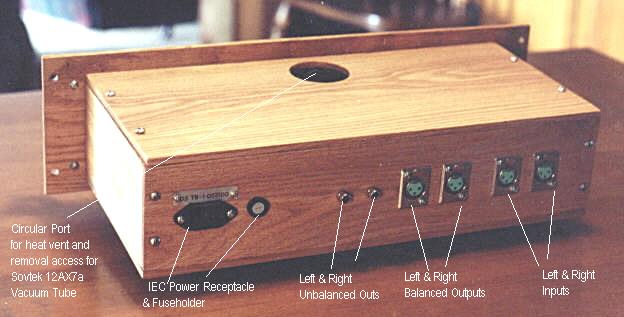
The rear panel of THE TB-1 is straightforward and uncluttered and reflects the ordered layout of the circuitry with sensitive input stages and associated connectors located furthest from the power supply end. The mic jacks are at the far right rear of the panel with the AC power connector at the far left.
As of late 2000, a design change for all DaviSound Tool Boxes now incorporates the standard IEC AC cord input connector with separate, detachable cord provided. This AC input connector block also includes built-in AC line filtering and noise suppression ahead of the built-in AC power supply transformers.
Internally, there are two power transformers feeding four separate DC power supply sections for Audio, Tube Filaments, and VU meter lighting. The audio supply is futher isolated and decoupled at each amplifier stage. Phantom power is derived from yet another, separate, isolated feed.
Female XLR connectors are provided for the balanced inputs and outputs with RCA jacks utilized for the unbalanced outputs.
Some users prefer to utilize SCREW TERMINAL rear panel connectors (not shown herein), in which case two sets of connectors are provided which are clearly labeled.
One of the added side benefits of using a WOODEN connector panel is the inherent ground loop prevention due to the isolation from a common chassis connection!
ELECTRICAL SPECIFICATIONS
|
Summary
POWER UP - IMPORTANT!- Always be certain that microphones are only plugged in or removed from the jacks with the PHANTOM POWER SWITCHED OFF ! This means that the phantom power supply will always operate into its intended load. It also minimizes offsets and spikes through the DC blocking capacitors which would occur if mics were plugged/unplugged with the supply on!
It is suggested that, since both channels receive phantom power simultaneously, you always employ a microphone, or dummy plug, into BOTH channels whenever phantom power is utilized. If a second mic is not desired, you may fashion a DUMMY PLUG by soldering a 100 to 1 KOHM resistor across pins 2 and 3 of a male XLR connector and insert it in the unused channel mic jack whenever a phantom powered mic is being used in the alternate jack.
It is advised that you ALWAYS adhere rigidly to the following procedure when powering up and operating your TB-1 amplifier. Turn both gain controls OFF - fully counterclockwise. Then, make certain that both power switches are off. Then to begin, turn on the main power switch- the UPPERMOST mini-toggle above the tube window . The GREEN LED and VU meters should light. Allow the tube stage to warm-up for several minutes.
If phantom powered condenser mics are to be used, then plug them into the appropriate jacks. Next, turn on the phantom power mini-toggle switch located BELOW the tube window. The YELLOW LED should light. Wait for about a minute before turning up the gain controls to allow the capacitors to stabilize and and DC offsets to minimize. Then, slowly turn up each respective gain control for a level check. It is possible, under certain conditions on initial rotation of the gain controls, for slight DC noise to be noticed during the rotation of the gain control until it is rotated a few times to bleed away any capacitive discharge. This is normal and unlikely to occur after the first few seconds after initial "fire-up".
Obviously, if phantom powered mics are NOT to be employed, than the above precautions do not apply.
We do not mean to imply that damage to the input stage is certain if you forget to follow procedure on occasion. On the contrary. However, it is good practice to follow such procedure religiously to minimize the chance of any accidental damage to sensitive FET input stages. It is also good practice to follow said procedure for the maximum protection of your condenser microphones as well.
Likewise, it is good practice to keep the Phantom Power Supply switched OFF whenever Ribbon or Dynamic microphones are utilized. For this reason, it is not advisable to use phantom powered mics in one channel simultaneously with non-powered mics in the other.
The TB-1, like all DaviSound Tool Boxes is designed and built for a lifetime of service with no problems. In the case of "Inner Tubes" models such as the TB-1, it is probable that tube failure will occur eventually. Tube life varies from tube to tube and under varying conditions.
With ALL TUBE GEAR it is suggested that you avoid frequent or rapid power up/power down sequences as this stresses the tube filaments. In fact, it may be desirable to leave the equipment on for long periods of time to maximize tube life and maintain stable operation characteristics of the unit. Some studios leave their tube gear on 24 hours a day for this reason. Your TB-1 is made to withstand this kind of operation!
In the unlikely event that your TB-1 should ever require service, you may contact us for shipping instructions. We will repair your unit, as per our standard, published warranty terms, for as long as you own it at no charge except for one-way shipping to us.
Please be advise that any unauthorized service attempts, modifications or modification attempts VOID all warranties.
Thank you for owning a DaviSound TB-1 "Inner Tube" Tool Box! Please stay in touch and keep us informed as to your application and give us your feedback on the TB-1 performance. Always feel free to send us your questions and comments at any time! We welcome and solicit your input!