The "BARNDOOR RECEIVER"


by Hayne Davis
Copyrights © 1997 - 2021 by Hayne Davis
The "BARNDOOR RECEIVER"
by Hayne Davis
Copyrights © 1997 - 2021 by Hayne Davis
2021 PREFACE- This little DIY article was first written and published on-line (on AOL) back in 1997. After AOL disbanded, I always thought I would get the chance to edit it, update the crude, hand-drawn diagrams, and put it on the DaviSound website. Well, obviously, that time never really came but I did decide to go ahead and put it up (prompted by a visitor email in 2021) "as was" with some minor ammendments along with the addition of a few more, original sophisticated TRF radio circuits developed in subsequent years which are all included below. I hope any radio enthusiast, "DIYer" will find it to be enjoyable, interesting and perhaps helpful. Thanks for reading and, if you care to comment, I'd be delighted to get an email from you!
(Original Preface) -
I had been associated with the creative and artistic side of radio for many years before I ever became interested in the technical side. In fact, even though I had been involved with the technical side of audio, early on, along with assorted creative endeavors, it was much, much later when the RF "tinkering" bug bit and I began to build experimental receivers!
It was in 1987, to be exact, when I was "breadboarding" my first working AM receiver, that I encountered a most rare accident. So rare, in fact, that I would NEVER believe it possible had it not happened to me and I am still in awe of such a coincidence even after all of this time!
As UNBELIEVABLE as this will sound to you I'm sure, it DID happen nonetheless! Unfortunately, I am the only witness, as well as the single participant, in this most unique event.
In the fall of that year, one of my custom produced radio commercials for Shakespeare antennas was running on night-time radio nationwide. On that eventful night, when I alligator clipped the nine volt battery and the headphones to my very first, primitive style receiver, it just happened to be broadly tuned to station WWL, well over 600 miles away in New Orleans, and the very first thing that I heard on my very first receiver was ...
MY VERY OWN VOICE!
WWL just happened to be airing one of my Shakespeare antenna commercials at the precise moment that I happened to "fire-up" my first home-brew receiver! That HAD to be a REAL RADIO FIRST!
(And, just perhaps, the greatest coincidence of all time!)
As Ripley would say... Now....on to the another "UNIQUE STORY" ...
"BELIEVE IT OR NOT!"
The story of the unique, "BARNDOOR RECEIVER" itself!
If you were to ask a radio "expert" to list the most desirable characteristics of a radio receiver, no doubt SELECTIVITY would be right at the top of that list.
Well here is another first ...
This article is about the virtues of a type of receiver which is, INTENTIONALLY, NON - selective, to just some degree! However, let me cast aside any doubts right away, at the outset, and emphasize that the tuning of this radio does NOT live up to its name in the "broadest" sense (pardon the pun!). It is certainly selective enough to be a very useful radio and, in fact, is probably the MOST selective, simple, single-stage TRF radio circuit you'll ever encounter!
This is going to be fun! So, settle back while I relate the story of how this radio came about. Then, get ready to break out the soldering iron and prepare to build your own version of the "Barndoor Receiver"!
As already mentioned, the radio bug bit me very late compared to most electronics enthusiasts. That is, the electronics side of radio since I had been in the programming/production side of radio for well over twenty years at the time the above episode took place. However, unlike most early experimenters who started out with crystal sets, my electronics enthusiasm began with a passion for state-of-the-art audio equipment since I was always interested in pro recording and the associated equipment.
A subsequent part of my career, through my company, DaviSound, has been devoted to the design and fabrication of such pro audio equipment. Until I was in my early forties, my chief concern with the technical aspects of RF ("Radio Frequency" for the uninitiated) was to keep it out of my sensitive audio circuits!
When I did get around to experimenting with simple receivers ... (I bypassed the obligatory, traditional Crystal Set in the sense that mine had a high-gain audio stage tacked on to it from day one!) ... I was hooked!
Like all of the other "youngsters" before me, I was fascinated by the sheer simplicity of primitive radio tuning circuits and the potpourri of acitivity which was "alive" on a long-wire, stretched outside to a nearby tree, and amplified up to speaker level on my workbench circuitry.I still am!
One day, after building one of my testbench "five minute wonders" peaked for a particular band, I was proudly showing it off for a friend who was a longtime RF designer and ham operator. He sort of snickered and pointed out that my receiver was "as broad as a barndoor".
He was referring to the comparative lack of selectivity and the, rather, broadband tuning of that particular circuit. What he did NOT realize, was that I had come to PREFER this type of shortwave receiver for "fun listening" over the more sophisticated, highly selective receivers which I had also successfully built and experimented with! The name that he coined stuck, though, and so did my fascination with these receivers!
ACTUALLY... MAYBE WE SHOULD HAVE CALLED THIS LATEST VERSION PRESENTED HERE
THE "GARDEN GATE"
INSTEAD OF THE "BARNDOOR"...SINCE IT CAN BE VERY SELECTIVE
ESPECIALLY ON THE LOWER BANDS
AND UNDER GOOD PROPAGATION CONDITIONS!
At first, I simply thought that I was addicted to the simplicity aspect of these basic receiver circuits. But, I subsequently developed some regenerative circuits which were HIGHLY sensitive AND selective by nature yet, component wise, they were just as simple as these "pet" TRF (tuned radio frequency) circuit variations.
My early experimenting eventually led me to my own successful versions of direct conversion receivers as well as minimum parts superhet designs. No matter what one designs and builds, there is always a tendency to develop the so-called "designer's ear" whereby one prefers to listen to one's own creations! Accordingly, I was always very enthused about the resulting performance of each of my evolutionary steps into radio circuit design.
Nothing, however, seemed to give me as much operating and listening satisfaction as those first, primitive, "barndoor" circuits. I finally figured out that I was actually HOOKED on the broadband performance characteristics of those earliest receivers.
When listening to a superhet, for instance, I missed the background "hash" of other distant stations on the shortwave broadcast bands. Whenever the "nature of the animal", international shortwave reception, caused one station to fade as they invariably do, I missed having another take its place on a nearby frequency as would usually happen with these less selective receivers!
While contemplating all of this, I decided that it was the NATURE of my "barndoor" receivers that I had come to love in my earlier days of experimenting! It was the simple fact that these were "band peaking" receivers moreso than traditional individual FREQUENCY receivers. But, these can be FUN and, actually, very useful too, as you will soon find out!
ESPECIALLY WHEN YOU LEARN TO MAKE THEM
AS A MORE NARROW BARNDOOR!
For example, I had perfected a 27MHZ CB receiver of this type which was selective enough to peak various sections of the band yet broad enough to receive anything, particularly the STRONGEST stations, on the band at any one time. Thus it performed like a "scanner" of sorts allowing reception of whatever was on the band.
Of course, during optimum signal conditions there was often a garble of signals all at once but, more often, the receiver would simply sit quietly until occasional local traffic would bark from its speaker one station at a time from whatever frequency was being transmitted!I also, later, built a small version with a tuning tank and antenna coupler designed esepcially to receive the 125 Mhz Aviation band. These "passive" (TRF) aircraft receivers have become quite popular in recent years but I built one of the first (the first I had ever heard of ) many years ago! (2021 Addendum- A schematic for a version of this ciruit is included herein below)
So, with all of the foregone justifying "propaganda" out of the way, let's get down to building a unique radio which is the final result of all my "back-to-the-drawing-board-efforts", to date, on coming up with the "perfect", yet simple, little multi-band barndoor receiver!
Now, conversely to our "BARNDOOR" thinking, while desiring these inherent broadband characteristics of a simple TRF tuning scheme to some degree, as mentioned previously, we ALSO want our receiver to be more selective than the typical crystal set!
Tests have confirmed that our circuit has acheived this and thereby provides VERY selective performance on the AM Broadcast Band and, quite often, surprisingly selective characteristics on the upper shortwave bands!
Always keep in mind, however, when operating your "barndoor", that it will, invariably, be at the mercy of the strongest signals reaching your antenna since it employs NO form of AGC and the strongest (loudest) signals on a given band at any one time will be the ones you are able to tune most successfully. Accordingly, it will be rather diffcult to tune in any nearby, weaker frequencies!
Also, its high sensitivity will often allow several stations to appear at a given portion of a particular shortwave band and this is, of course, most noticable in the upper band regions as the frequency wavelength becomes shorter and shorter. This is what provides us with the, somewhat, broadband "scanner effect".
Whenever two or three signals happen to be detected at once, then perhaps, like me, you will enjoy experimenting with what is known as the "cocktail party effect" of mentally tuning in one conversation (or, in this case, one broadcast) at a time!
There is a lot more detail provided on what type performance you can expect covered under the "PERFORMANCE" section, which is forthcoming. Also, of course, on this website you will have an advantage that the original reader did not have with the provided audio samples link which will, also, be forthcoming! But, for now, let's move on to our CIRCUIT DESCRIPTION!
BELOW IS ... VERY ROUGHLY DRAWN ... "FIGURE 1"

This is, at a glance, about as simple as it gets. But, the KEY to performance with this circuit...
is in the COMPONENT VALUES! So the values given should be closely adhered to!
These values are listed in the parts list
and, sometimes, referred to in the following text as well.
The HEART of our receiver is a basic RF amplifier front-end which is built around the unbiquitous 2N-3904 transistor, which we also employ in the following audio stage as well.
This type of receiver requires a fairly long antenna for exceptional performance, especially for the lower frequencies. We used a thirty foot high by seventy foot long "inverted L", longwire, with AMAZING results!
We have, however, tested this receiver with a simple ten foot section of wire draped across the room with pretty fair performance on the upper bands.
Also, another version was built and installed in an old console cabinet and it used the existing wire loop, which was wrapped around the interior perimeter of the 4' by 2' cabinet box, with fair results. However, to REALLY experiment with the performance of your radio initially, use as long a wire as is possible for your antenna, preferably stretched outside your window, to an upper limb of a nearby tree!
REFER TO FIGURE 1 FOR THE FOLLOWING DESCRIPTION ...
The antenna signal is is coupled to the base of Q1 via a small coupling capacitor, C1. Our RF transistor, Q1, is used in the common emitter configuration with a self bias scheme provided by feedback resistor R2.
NOTE: BOTH our RF transistor and AUDIO gain transistor use this self-bias method which is the simplest, with lowest parts count, you can utilize- a goal of our project. The values of the collector resistor and feedback resistor employed with this method allow the DC voltage at the output junction of the transistors to stablize at, roughly, HALF THE SUPPLY VOLTAGE, no matter what supply voltage is utilized.
WE RECOMMEND A 12 VOLT, REGULATED POWER SUPPLY FOR THIS PROJECT, BY THE WAY.
However, it will work with a supply of from 9 volts to over 24 volts!
(The higher voltage supplies will create slightly more transistor gain.)
In our RF stage, R1 = 2KOHMS, and R2= 510KOHMS. These values may be increased slightly, say up to
4.7 K and 1MEGOHM, as long as the ratios are comparable. However, this would cause some increase in gain which might cause the RF stage to have a greater tendency towards instability and sporadic oscillation.
C3 provides RF by-passing, shorting any RF in the supply line to ground, and it should be located as physically close to R1 as is possible in your layout.
NOW, THE IMPORTANCE OF THE VALUE OF THE COMPONENT C2
CAN NOT BE OVER- EMPHASIZED!
Its value, more than any other circuit factor...
governs the SELECTIVITY of the circuit
as it matches to the following tuning tank circuit!
In order for the tuning tank circuit to maintain a maximum "Q", the loading by the previous stage must be kept to a minimum. Therefore, a very small value of capacitance is required for coupler C2. The circuit would work with only slightly varying characterisitics with values from 2 pf up to about 10 pf (even 22 pf for radios restricted to lower bands).
We chose 5 pf for our circuit as it offers a good compromise of sensitivity versus selectivity all across the bands.
The possible exception to this rule would be at the lower end of the AM Broadcast Band where a higher value would probably be better. Keep this in mind if you design such a circuit exclusively for MW or LW reception and you may want to choose a 10pf to 27pf value for C2 in that case. The "squeezed" RF signal passes from C2 and is developed to resonance across the tuning tank of L1 - L4, in parallel with CT.
One of the more unique aspects of our particular design is in the choice of components which comprise the tuning tank.
As opposed to cumbersome hand-wound coils or other inductors, we have elected to use small, molded chokes for the inductors L1-L4 in this circuit!
Also, since our experience with these circuits in many variations has shown that the highest Q, and resulting highest selectivity of such simple tanks, comes from a high capacitance to inductance ratio (up to a point, whereby the loading capacitance starts to severely hamper the efficiency of the tank and the sensitivity suffers) we utilize TWO SECTIONS of a dual 365pf variable capacitor strapped in parallel for CT).
You can even use up to a THREE section variable but watch for some of that loading on the lower frequencies of a given band as the capacitor plates are rotated to full mesh.
You can, of course, also choose to use a SINGLE section 365pf tuning cap but, in that case for slightly improved "Q", I would suggest placing a small capacitor in parallel with the air variable, say around 47 pf to 100 pf. Even so, as already explained, nothing beats the "Q" of multiple stage air variable tuning capacitors strapped in parallel!
It goes without saying, of course, that the capacitance values directly affect the frequency being tuned as they vary across a given, fixed inductance. So, obviously, if you add capacitance across a given inductance to increase the "Q" you are simultaneously lowering the overall frequencies to which the respective tank will tune with the given coil (choke) inductance.
L1-L3 are all 1 micro-henry molded, miniature, pre-fabricated RF chokes and these three are in series with L-4, a 100 micro-henry choke.
The use of the small chokes, as oposed to other type inductors, allows convenience, repeatable predictablility of the circuit and, also importantly, allows an easy method of mounting the inductors directly to a band selector switch.
While these small chokes might not always offer the greatest "Q" (efficiency) of coil type for a given band, they have shown to be a good compromise for convenience, predictability, repeatability and mounting capability. However, in all honesty, you really SHOULD try winding some coils for yourself and if you are at all fascinated by this aspect of radio construction, by all means GO FOR IT! In that case experiment with winding your own coils!In fact, if you are pleased with the selectivity and sensitivity of the receiver using the chokes for tuning coils, then you will REALLY be astounded by the improvement in both areas when properly winding a coil onto a high "Q" ferite, Toroid core! For single tuned TRF radios, coils wrapped on ferriite Toroid forms with magnet wire are hard to beat! (2021 addendum- such subsequent circuit design schematics are shown below)
CT, the variable tuning capacitor which is in parallel with L1-L4, is an "air variable" of the type used in older broadcast receivers and is available from several sources including the one mentioned in the parts source section. The best (most fun!) solution, perhaps, is to "lift" (remove) one from an old, junked receiver. But, these old receivers are becoming increasingly rare "animals" these days! Of course, you could use varicap (varactor) tuning diodes, as is often done nowadays, should you desire. However, while convenient, varactor diodes have disadvantages in that they do not offer very high "Q" while they also vary in capacitance with supply voltage. So, unless you use a reguated power supply for them, they will change in value resulting in a change in tuning range as the battery supply weakens!
Notice that we have utilized a THREE POSITION SWITCH to allow for band switching. This can be any three position switch, slide or otherwise, but I prefer ROTARY types in these applications and always use a rotary band-select switch arranged so that full left position is the highest band with full right being the lowest band, analogous to capacitor tuning rotation.
Observe from Figure 1 that position 1 shorts all of the chokes out except for L1 which provides 1 micro-henry of inductance across our tuning capacitor. This will alllow you to tune from , approximately, 5MHZ to 16MHZ depending, of course, on the exact value of your tuning capacitor.
This upper shortwave band will particularly active in the daytime hours in the northern hemisphere picking up international shortwave broadcasts as well as other interesting "surprise" transmissions from time to time!
With the selector switch in the next position, a total of 3 micro-henries of inductance is switched across the tuning capacitor and the resulting tank now tunes from about 10MHZ down to near 3 MHZ. This lower SW band will be more active in the evening hours well after sunset. In the final swiching position, all the chokes are now across the tuning capacitor. of course, the large 100 microhenry choke now becomes the dominant inductance and allows tuning from just above to just below the standard AM Broadcast Band with the actual range determined by the exact values of your tuning capacitors. Note to cover the entire broadcast band with just a little over 100 micro-henries inductance, you will need about 750 pf total capacitance!
Due to the mathematical relationships involved, it is possible to find an old defunct radio cabinet, with the tuning capacitor intact, and build your circuit into the cabinet using the existing tuning capacitor, (all sections in in parallel and in parallel with trimmers, or extra "padders", to "tweak" the tuning on the nose) and construct a two-band switchable receiver that uses the existing dial as a readout. If you use a 1 micro-henry choke for the SW band, and a 100 micro-henry choke for the broadcast band, the dial can give you a close to accurate reading with the markings referring to Megahertz in the shortwave mode and Kilohertz in the broadcast mode.
Referring again to Figure 1, after the signal is tuned to the desired frequency, it passes to the signal diode, D1, which is used as a standard detector. At this point, we have audio detection via rectification of the carrier wave and the remaining portions of the carrier wave are then filtered out by capacitor C4.
The audio signal is fed via P1, the volume control, to the audio amplifier stage which is also comprised of a pair of 3904 transistors forming a simple, class A, audio amplifier. While it might be desirable to add yet another gain stage, such as a low-watt IC power amp for driving a speaker to room filling volume, this amp, alone, will provide adequate volume for headphone listening and can even drive small speakers at a fairly low volume level.
I chose discreet transistors for this illustrative design for several reasons. One consideration was to provide the opportunity for amateur builders to learn from utilizing them in a simple, bare-bones, discreet amp configuration since they are seldom seen used anymore for published projects in today's world of the "King IC". Secondly, they require a minimum of support components in our circuit and, finally, because I had hundreds of them in my spare parts box salvaged from old circuit boards!
Q2 forms the first audio stage and it is very similar to the Q1 RF configuration. The audio is coupled to the base of Q2 by C5 and amplified to just about 60 db (assuming a high enough supply voltage) by the ratio of R4 to R6. R6 can be eliminated at lower supply voltages for maximum gain (but slightly higher distortion)-the emitter of Q2 being grounded direct.
R5 provides self bias to the base and is strapped with feedback capacitor C8 which limits the high freqency bandwidth with negative feedback at the higher audio frequencies. This aids stability in the audio section, reduces distortion and, doing tripple duty, provides further RF filtering for the circuit as a whole.
The amplified signal from Q2 is then direct coupled to the base of Q3, which is configured as an emitter follower, thereby providing the circuit with impedance transformation and current gain at the output. The result is an audio amp with the desirable characteristics of a high impedance input for minimum loading and a low impedance output for maximum drive capability.
Q3 "sees" R4 doing double duty as its base bias resistor while serving, also, as the collector resistance for Q2. The output signal is taken across R7 via coupling capacitor C9. A value of 10 micro-farads is shown for C9 but this can be raised to a higher value if maximum drive and low frequency response is desired into low impedance loads such as an 8 ohm speaker. If that is the case, a 100 micro-farad to 1,000 micro farad component may be utilized, the latter giving full fidelity low frequency response at maximum power output.
It should be noted, however, that if speakers are to be employed, it really would be more desirable to replace Q3 with a power transistor, such as a TIP 31 or equivalent, as the 3904 would be greatly stressed to serve as a power amplifier for a sustained time period. For driving a very small, low wattage, (3 1/2", etc.) type minature speaker, the circuit is adequate as is with a 12 volt supply (higher supplies might cause the final 3904 to run excessively hot under load stressing it to early failure). But, in fact, for speaker drive it would really be much better to also add another gain stage similar to the Q2 stage and then go ahead and "beef up" Q3 to a power transistor.
R8 is simply a DC "pull-down" resistor to keep the output at ground potential thus avoiding a "pop" when headphones, or subsequent stages, are connected or disconnected to C9.
Components R3,C6 and C7 form a power supply decoupling network. The final overall result here is a very stable, very clean, low-noise, "bare-bones" audio amplifier which may be copied and utilized in many other applications that require high gain amplifiers with similar characteristics (such as unbalanced microphone preamps)!
NOW AS WE MOVE INTO CONSTRUCTION TECHNIQUES ...
PLEASE REFER TO FIGURE 2 ... BELOW
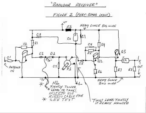
Actually, it is a fairly simple matter to wire up the circuit and perf board construction is perfectly acceptable for a "rapid-fire" assembly method. The above layout is shown as a guide for utilizing point-to-point wiring with components mounted on perf-board. The best technique, remembering the old rule, "ground follows signal", is to layout the circuit on perf board in much the same way that the schematic is drawn in left to right fashion. The above, rough drawing displays such a layout.
The RF stage is at the extreme left with the audio stages following in succession to the right of the circuit board. Ideally, tie a heavy gauge solid wire for the ground bus-bar to the bottom of the board and use a similar bus-bar at the top for the V+ supply rail. Alternately, press-on adhesive copper strips may be used as a running ground plane and voltage rail.
We have repeatedly built this complete circuit on 2" by 6" perf board sections, standing resistors on end for compact layout. Feel free to spread this out somewhat, however, if desired and you can even separate the RF and Audio boards if necessary. However, keep connecting leads tightly twisted and as short as possible and the same goes for any remote mounted controls.
It is best to mount the chokes directly at the tuning capacitor tie point, wired in a neat series cluster. The single end of the cluster can be direct soldered to the capacitor case ("low", grounded, side). Run a wire from this junction back to the circuit board ground bus at the RF end of the board, NOT at the audio end (REMEMBER:"Ground follows Signal!). See the paragraph on down which describes connecting the tuning tank to the circuit board using a parallel wire ribbon cable pair.
This "Ground Follows Signal" rule is probably the best tip offered in this article for this project, or any similar project, where small AC signals are employed! The other rule is: "Keep ALL Signal Wires Tightly Twisted"! Believe me, employing these two "old-timer" tricks, often overlooked, will save you countless hours trying to run down the source of hum, instability and other "gremlins" in sensitive circuitry! Twisted pair signal routing keeps crosstalk and hum pickup, due to inductive coupling, reduced to a minimum...
(actually moreso than shielded coaxial cable which is more effective for capacitively coupled interference).
This twisting works by phase cancelling any inductive pickup along the pair by forcing it out-of-phase by means of the twisted wire.
Now, if you notice the note at the left lower area of Figure 2, we advise you NOT to twist the leads going to the tuning tank but to USE PARALLEL WIRE, RIBBON CABLE PAIR for this connection. This is because the tuning tank might possibly "see" the twisted wire as a resonant coil at certain RF frequencies thus causing undesired, and unexpected, tuning resonance or rejection at these frequencies! Actually, this is unlikely but possible. One way to use the "twisted shield" in this case, is to connect the ground wire of the twisted pair at one end only and use a separate wire for the continuity ground connection.
Maximum performance for this circuit, as already mentioned, will result from the use of a 12 volt, regulated supply. However, any well filtered supply from 9 volts to 18 volts may be used as well as a standard nine volt battery. However, battery life might be somewhat short due to the current draining, Class-A audio circuitry employed.
EXPECTED PERFORMANCE
Before fully describing the comparative performance of such a simple receiver, it is important to consider radio reception in general, epsecially the nature of the shortwave bands.
Shortwave recption with our little "Barndoor" circuit can be quite rewarding and what, at times, might be misconstrued as "behavior" of the radio (good or bad) might actually be the "behavior" of the conditions of the shortwave bands!
It is suggested that beginning readers investigate the countless references on radio and shortwave reception in general. The more one knows and understands the subtleties and complexities of the propogation medium, the more one will get out of the hobby of exploring the shortwave bands on any level!
In regard to simple receivers such as ours here, nothing can be more perplexing than wanting to share the enthusiasm for a home brew creation's performance that you experienced on a given day only to find, when trying a demonstration for someone, altogether totally different performance the next day.
For example, I had such an experience while trying to prototype this project and document the performance results. Fortunately, the first day I built up my protoboard circuit, band conditions, while not excellent per se, happened to be near perfect for this project! As I tuned across the shortwave band that mid-morning I was actually astonished at what I was hearing! The receiver tuned about a dozen stations, evenly spaced apart, with apparent selectivity very similar to what is normally encountered on the broadcast band at night. And that can be very good and selective, indeed!
I lisened to the BBC, Radio Canada, tuned several foreign language broadcasts in French, German and others I could not identify. I also heard WWV at 10 MHZ along with the usual USA paid religious broadcasts that proliferate from this country nowadays. Each station could be heard with minimal interference, if any at all, and each occupied a very narrow area of tuning capacitor rotation. In short, I thought to myself that this must be better performance than could normally be expected.
That turned out to be quite true since the very next day conditions were TOO good (propogation conditions that is) for the old "Barndoor" to handle and, while I could still tune MANY stations all across the dial, I was usually hearing several at each location with very little separation at all. At the very top of the band, all I got was a conglomeration of "hash" with no tuning capablility whatsoever.
Then, the third day when I turned the set on, I had to crank the volume wide open to hear anything on the SW band and only two fairly strong signals could be received at any location across the band. And, each of them occupied a very broad area of the tuning capacitor rotation.
Three days and three entirely different performance sessions altogether! It's useful to know this so that you won't think your circuit is performing incorrectly on your first test if you don't hear anything like you anticipate or like I describe and demonstrate!
AMATEUR ("HAM RADIO") RECEPTION
While this circuit, as it stands, will never be quite sensitive enough or selective enough to provide any form of serious listening on the amateur bands, I can report (and will demonstrate in the audio samples) that I have copied many AM transmissions and "QSOs" on ALL of the "Ham" bands in the range that the receiver covers. When the conditions are just right, and with a proper antenna and coupling (perhaps using a preselector for enhancement-i.e. another tuning tank between the antenna and the RF amp stage), you will be amazed by what you can hear once you become familiar with the tuning characteristics!
Of course there is no BFO for CW or SSB reception but, if you play with these simple radios as long as I have, you learn, almost, to understand many SSB transmissions as they stand! You can also tune CW and monitor the "PHFT PHFT PHFT" of carrier wave morse code transmission. Very often, these signals will beat against other signals and cause enough heterodyne action to enhance their intelligibility. There is a lot of amusement be had in trying to obtain a signal "catch" in this fashion!
So, we have just described the performance plusses and limitations for a simple TRF receiver such as our "Barndoor". Sometimes this little radio will amaze you with its VERY useful performance! Other times, under different conditions, you'll find yourself turning it off in disgust while going to get your more sophisicated receiver in order to hear something you've been trying to steadily copy but can't.
With a good antenna, you can ALWAYS count on night-time reception to be pretty good ESPECIALLY on the AM Broadcast Band (unless you live very close to a local station!). As I write this, it is approximately 5:00 PM in the late winter in the southeastern United States and I am listening to a loud and clear signal on 560KHZ from a 5,000 watt broadcast station about forty miles away. There is NO noise or interference whatever.
I am about one air-mile away from a local 1KW station on 1520 KHZ, which is also notorious for spurious emissions, and about three miles from another 1KW station on 1240 KHZ. I can satisfactorily tune all these stations with this circuit and my longwire though there is some slight interference between the two upper band stations at times.
Now there is one area that we should mention, in closing, where simple TRF receivers offer SUBSTANTIALLY SUPERIOR PERFORMANCE over superhets or all other designs! AUDIO QUALITY of our "Barndoor" is far superior to other forms of AM recption and can be very HIGH FIDELITY, indeed! The only real limit is the rest of the chain in your system and, usually, the main quality deterent is the low integrity of the signal itself that is being broadcast by the AM station. Very few of today's AM stations broadcast with the attention to bandwidth and dynamic range that they could, or should, but the quality of a well-tuned, well transmitted, AM signal can be quite amazing when heard on a TRF receiver! This is especially true if all you have ever heard before is a typical, narrow band, distorted, commercial AM receiver!
The audio quality that you will hear from this radio, with no intermediate frequency conversion and the distortion this process brings with it, no IF filters and the limited narrow bandwidth they provide, and no automatic gain control with resulting coloration, will be the very best audio that the transmitting station can provide. Because THEY, the broadcast station, will be the sole limiting factor to the quality! Naturally it will vary from station to station but, it can be very, very good.
It would be well worthwhile for radio veterans to build this circuit since many enthusiasts have no real idea of the actual performance capability of our design. Some will look at it, on paper, and scoff at it without ever having tried it, falsely concluding this, that or some other thing to themselves in the process.
That's a shame, because building such a receiver can be VERY eductaional and revealing ESPECIALLY if you use the opportunity to experiment with performance variables offered by substituting different types of inductors and various capacitance/inductance ratios and documenting the results of all of this.
If so, I GUARANTEE you will, at the very least, find out some things to be quite different than what you had presupposed!
By the way, while an earth ground (that metal cold water pipe you are always hearing about) will offer about a 3 DB gain increase at the lower frequencies, and in some cases help with circuit stability, it is not that noticable at high frequencies and certainly not a necessity for good performance, in spite of what you've heard. Try it both ways and find out!
In conclusion, I can say that this simple design, offered here, is about as amazing a performer as any simple, single tuned RF stage could ever be! I insist it will outperform any similar circuit I've ever seen published including all those with the famed ZN414 IC, all those MPF 102 FET "infinite impedance" detector radios, and most regenerative designs that I have experimented with.
The bottom line is this: It will provide endless hours of fun... curiosity and education for the builder, that's a promise.
So, open up your own "BARNDOOR" ... We told you, in the last section, that the key to selectivity for this receiver was largely due to capacitor C2 and its proper value.
and you will be amazed at what finds its way in over time!
BARNDOOR RECEIVER CONCLUSION
ENHANCEMENTS
The whole idea for this project was based on the old...
"keep it simple, stupid" concept!
And now we're going to tell you how to "complicate it" ?!!?
WELL...
JUST SLIGHTLY!
For clarity, we've included "Figure 1", again below ...
Actually, capacitor C1 has something to do with this also.
We list the value for C1 as 100pf. With a receiver of this type, that's about as large a value as you would ever want to employ, especially with a longwire antenna. That's because the larger value of C1 couples more antenna signal to the RF amplifier stage and, thereby, makes the receiver more subject to overload by strong signals from the antenna.
Also, the impedance characteristics of the antenna itself interact with the impedance of C1 causing varying degrees of performance at various frequencies. So, one "enhancement" to our simple receiver would be to make C1 a VARIABLE capacitor with varying capacitance from, say, 5pf to 150pf.
Alternately, you could add a stepped switching arrangement selecting assorted values of small capacitors at intervals within this range (say, 5pf, 10pf, 25pf, 47pf,100pf). The smaller values would offer much better performance at the higher frequencies of the SW spectrum.
This, in effect, creates an "antenna tuner" for our "front-end".
Now, we could ENHANCE this even further by adding another tuning tank after this coupling cap and have it coupled to the base of Q1 by yet another small coupling capacitor (CX)! A simpler compromise to another complete tuning tank, is to pick a switchable, pre-set, resonant "tank" circuit for a desired band and switch it in whenever you tune that desired band.
A good example of this would be to choose a 2 micro henry inductance in parallel with a 300 pf capacitor and make this parallel circuit "tank" switchable to RF ground from the junction of C1(changed to 47pf) and an extra coupler CX (10pf).EXAMPLE: -----]c1(-----*---]cx(-------to base of Q1
* = (to top of tank, then to ground via switch)
Switching in a "pre-selector" tank comprised of the values given in our example would give enhanced performance with decided pre-emphasis for the 40 meter ham band.
Just WHAT does all of this "enhance"? Actually, it enhances both sensitivity AND selectivity to add a means of tuning and matching, more precisely, the antenna to the RF stage and subsequent main tuning tank! Adding such an arrangement will make it possible to bring in smaller signals, for example the ham band signals, with better separation and sensitivity!
PARTS LIST:
Resistors(all 1/4 watt)-
R1 = 2 KOHMS
R2 = 510 KOHMS
R3 = 47 OHMS
R4 = 10 KOHMS
R5 = 1 MEGOHM
R6 = 10 OHMS
R7 = 100 OHMS
R8 = 4.7 KOHMS P1 = 50 KOHM potentiometer
Capacitors (all rated 25 volts or higher)-
C1 = 100 pf ceramic disc or silver mica
C2 = 5 pf NPO ceramic disc
C3 = .1 mf ceramic disc
C4 = .01 mf mylar film
C5 = .22 mf mylar film
C6 = 220 mf electrolytic
C7 = .1 mf ceramic disc
C8 = 470 pf ceramic disc
C9 = 10 mf to 470 mf electrolytic - CT = 15 pf to 365 pf dual ganged, air-variable
Inductors-
L1 - L3 = 1 uH molded RF choke
L4 = 100 uH molded RF choke
Semi-Conductors
Q1 - Q3 = 2N3904 Transitor
D1 = 1N34 Germanium Signal Diode
PARTS SOURCES: SOURCE LINKS:
Most parts are available individually from any of the source links given below. If you prefer, a complete kit of brand new, tested, selected parts...
minus the tuning capacitor, is available from DaviSound for
$25.00 postpaid (USA ONLY).
For order instructions, use the email address below. I'll reply.
DAVISOUND JAMECO ELECTRONICS ALL ELECTRONICS ALLTRONICS CIRCUIT SPECIALISTS DIGI-KEY CORPORATION
EMAIL ME ... "WRITE AWAY"! - DaviSound at DaviSound dot com OTHER LINKS OF INTEREST ...
DAVISOUND "MasterPieces"
CRYSTAL SET SOCIETY
RADIO CIRCUITS
BARN DOOR RECEIVER
AUDIO RECEPTION SAMPLES
*NOTE*
This section may be updated occasionally when opportunity permits
for recording further examples of the Barndoor in action.
In order to get some examples up as soon as possible...
the following segments are offered, though they are
NOT, BY FAR, exemplary of the receiver at its best!
Unless specifically noted otherwise, all of these first examples were
recorded during the third week of December 1999. In order to grab these
quickly, "on the fly", rather crude recording techniques were used.
Instead of utilizing a line input into the tape deck, an old portable cassette deck with
built-in mic was simply placed closed to the speaker of the receiver.
This being the case, also keep in mind that the automatic gain control
of the tape deck came into effect during recording thereby leveling
the dynamic range of the Barndoor reciever
and greatly disguising its typical performance in that regard.
FINAL POINT OF NOTE
The version of the receiver utilized for the samples herewith
is identical to the circuit given in the article
except that this version utilized a larger selection of band switching
positions (more chokes) and used a three section 365PF tuning capacitor
with all sections strapped in parallel.
(2021 Addendum) - These old samples were originally recorded using the Internet audio medium of the day, "Real Audio". The outdated .RM files are still playable using some available applications such as VLC, which you will need in order to play them.
SAMPLE ONE - 27MHZ - CB SKIP
This segment was recorded around mid-day and
illustrates only one rather loud skip signal.
This was using the uppermost bandswitch position of our unit with the tuning
capacitor very near the upper end of its rotation. It was being tuned
against our first choke ... a .25 micro henry choke ...
with NO pre-select enhancement utilized.
The antenna coupler (C1) was 10pf. CLICK HERE
SAMPLE TWO - ALL BAND SW
This is a six minutes plus clip of general shortwave reception
on our cabinet model Barndoor Receiver.
It is not the best, nor the worst, performance by the radio as
determined by varying conditions explained in the article.
What you hear is general, random tuning starting at about 16MHZ band switch position
with the tuning cap "full-out", for the upper extreme, and then slowly tuning downwards.
This is repeated at every bandswitch position down to just about 5MHZ.
Whenever a relatively loud, clear signal was detected the tuning was stopped
and we paused briefly to demonstrate the reception at that point.
Some interesting "catches" were obtained on this quick effort including
a BBC sportscast and a tidbit from a WHRI radio drama broadcast.
Missing, however, are examples of the rather typical loud and clear broadcasts from
Radio Canada International, Radio Netherlands, Radio Japan and WWV to name a few!
Hopefully, we'll have some samples of these up at a later time.
To hear the general shortwave reception clip CLICK HERE.
SAMPLE THREE - AMATEUR BANDS RECEPTION
Once again, in a hurried attempt to get something up, this is... BY FAR
NOT the best reception examples of these bands...
but only what I could capture
in hurried fashion with limited effort.
Somewhere...(filed away for "safe keeping" in a location I can't presently remember)...
I have a one hour cassette of a great "Classic Exchange"
recorded in March of 1998. This was a Sunday afternoon of non-stop, "old-time" AM net exchange on 75 meters and the signal reception was exceptional.
As soon as I can locate this tape, I'll get some of it up in Real Audio format!
For now, you can hear what I could capture, with limited time, the third week of December 1999!
It begins with some brief 75 meter code transmission...
Then the clip consists mostly of one morning's fairly marginal reception of
40 meter traffic. This is followed by a very short burst of 75 meter QSO recorded on Saturday December 18, 1999.
To hear the amateur bands reception samples ... CLICK HERE
Medium Wave standard broadcast reception on this receiver...at night...
utilizing a longwire ... is very much comparable to any standard superhet.
However, I will try to have some samples of this, also, whenever time/opportunity allows.
Even though these segments I have presented here are not the very BEST examples of what you can acheive with the Barndoor...
They should provide adequate representation to show that such a receiver is well worth the minimal effort required to construct it! Perhaps the BEST examples of performance will be acheived when you "fire-up" YOUR OWN version for the first time! That is the very best way to "sample test" it!
Good luck ...and thanks for reading!OTHER LINKS:
2021 ADDENDUM- SIMILAR AND FURTHER DEVELOPED
ORIGINAL DESIGNS BY THE AUTHOR


AMERICAN RADIO RELAY LEAGUE
SHORTWAVE LISTENER'S GUIDE
SHORTWAVE AREA AT ART BELL SITE 
DISCLAIMER - None of the outside links herein were tested as of the 2021 repost of this article!
I apologize for any likely dead links after all these years and thank you for your understanding! Hayne Davis